
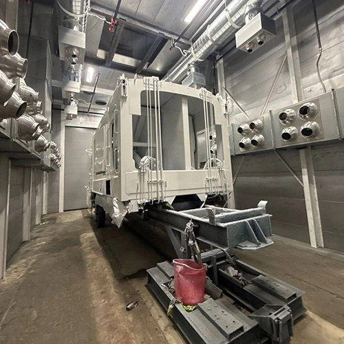
Finishing equipment buyers often compare open-face, crossdraft, and downdraft booths as if they were three competing tiers on a single ladder. That framing creates immediate confusion because the names describe two entirely different mechanical decisions.
"Open-face" defines the booth’s enclosure style and how parts enter the work area. "Crossdraft" and "downdraft" describe the path ventilation air travels through the cabin. Because these terms address separate design choices, they are not mutually exclusive. A common open-face booth, for instance, uses horizontal crossdraft airflow: it draws air across an open front threshold and exhausts it through a rear filter bank. Conversely, enclosed booths can utilize crossdraft, downdraft, semi-downdraft, or side-downdraft airflow paths.
Matching equipment to your finishing operation requires evaluating enclosure access on one axis and airflow direction on the other. Evaluating these variables independently prevents paying for civil floor work your process does not justify or selecting an open configuration that exposes high-gloss coatings to airborne plant debris.
Separating Enclosure Access from Air Direction
Enclosure access determines how workpieces enter the cabin and how exposed the finishing zone is to the surrounding facility. Airflow direction dictates how overspray and solvent vapors move away from the operator and the workpiece toward exhaust filtration.
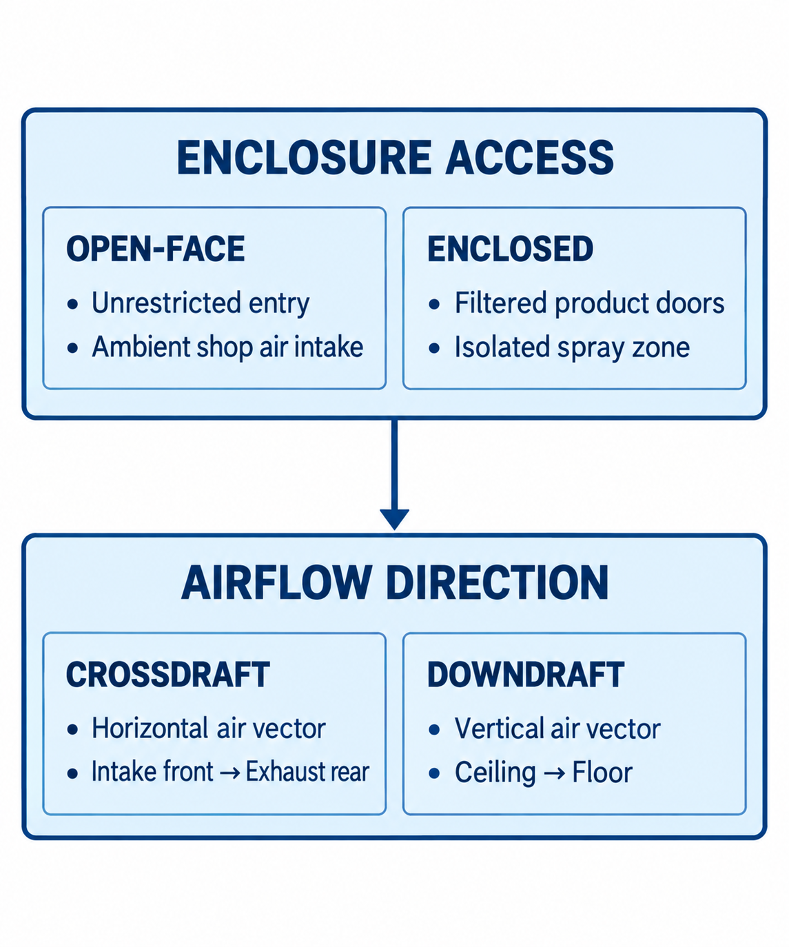
Diagram description
- ENCLOSURE ACCESS
- OPEN-FACE
- Unrestricted entry
- Ambient shop air intake
- ENCLOSED
- Filtered product doors
- Isolated spray zone
- AIRFLOW DIRECTION
- CROSSDRAFT
- Horizontal air vector
- Intake front
- Exhaust rear
- DOWNDRAFT
- Vertical air vector
- Ceiling
- Floor
- ENCLOSURE ACCESS → AIRFLOW DIRECTION
- Intake front → Exhaust rear
- Ceiling → Floor
- ENCLOSURE ACCESS
- OPEN-FACE
- ENCLOSED
- OPEN-FACE
- Unrestricted entry
- Ambient shop air intake
- ENCLOSED
- Filtered product doors
- Isolated spray zone
- AIRFLOW DIRECTION
- CROSSDRAFT
- DOWNDRAFT
- CROSSDRAFT
- Horizontal air vector
- Intake front
- Exhaust rear
- DOWNDRAFT
- Vertical air vector
- Ceiling
- Floor
- ENCLOSURE ACCESS upper container has two parallel columns: OPEN-FACE owns Unrestricted entry and Ambient shop air intake; ENCLOSED owns Filtered product doors and Isolated spray zone.
- Container downward arrow to AIRFLOW DIRECTION lower container with CROSSDRAFT owning Horizontal air vector and Intake front → Exhaust rear; DOWNDRAFT owning Vertical air vector and Ceiling → Floor.
- No arrows from individual access columns to airflow columns.
When evaluating open-face booth configurations, you are choosing an open structural envelope designed for rapid part loading, conveyorized finishing lines, or structural components. The airflow path inside that open envelope remains horizontal: shop air enters through the face opening and travels toward an exhaust plenum on the back wall.
When evaluating enclosed designs, you are choosing an isolated environment sealed by filtered entry doors. Inside that enclosed cabin, the airflow may be horizontal (intake doors at the front, exhaust bank at the rear) or vertical (intake ceiling filters, exhaust floor grates). Selecting a booth requires deciding how sealed your process needs to be, followed by selecting how air should move past your parts.
Enclosure Access: Open-Face vs. Enclosed Finishing
The choice between open-face and enclosed finishing balances parts handling speed against airborne contamination control.
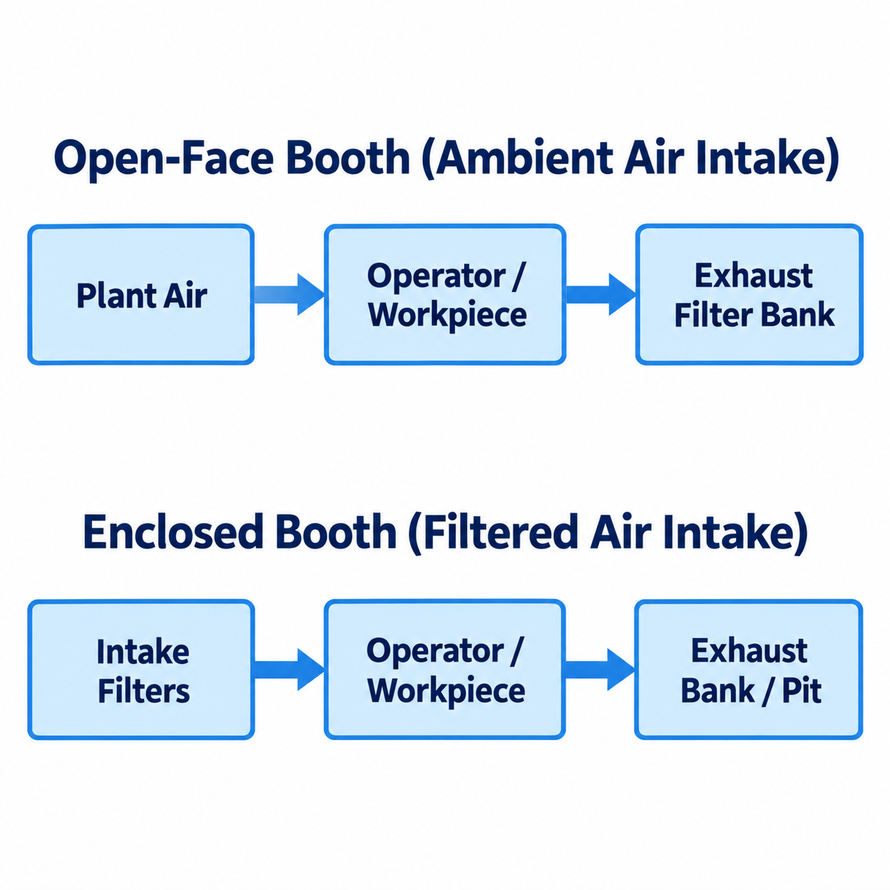
Diagram description
- Open-Face Booth (Ambient Air Intake)
- Plant Air
- Operator / Workpiece
- Exhaust Filter Bank
- Enclosed Booth (Filtered Air Intake)
- Intake Filters
- Operator / Workpiece
- Exhaust Bank / Pit
- Plant Air → Operator / Workpiece
- Operator / Workpiece → Exhaust Filter Bank
- Intake Filters → Operator / Workpiece
- Operator / Workpiece → Exhaust Bank / Pit
- Open-Face: Plant Air → Operator / Workpiece → Exhaust Filter Bank
- Enclosed: Intake Filters → Operator / Workpiece → Exhaust Bank / Pit
- No cross-panel links
Contamination and Facility Air Exposure
Open-face booths pull untreated plant air directly into the spraying envelope. If your shop environment generates airborne sawdust, grinding grit, blast media, or overhead door drafts, that particulate travels across the wet workpiece before hitting the exhaust filters. For primer coats, structural steel, agricultural components, or industrial machinery, this exposure is often acceptable. For multi-stage clearcoats or mirror-finish industrial topcoats, ambient plant dust causes surface defects that require labor-intensive sanding and buffing.
Enclosed booths isolate the application area. Intake air passes through engineered filter media on entry doors or overhead plenums, catching particulate down to target micron thresholds before the air touches the wet finish. Containment also depends on the ventilation design, operating conditions, and enclosure openings.
Workflow and Material Handling
Open-face booths provide immediate physical access. Operators move parts in and out on overhead monorails, roll carts directly into the face, or walk along a long structural beam without opening, latching, or clearing swing doors. For operations handling irregular weldments, high-mix subassemblies, or conveyorized continuous coating, open-face construction can reduce loading delays at the booth threshold.
Enclosed booths require clearance for hinged swing doors, bi-fold doors, or roll-up roll-down fabric doors. Loading a large trailer or vehicle requires sufficient apron space outside the booth to align and push the load through the entryway.
Operational Footprint and Energy Consumption
In standard product literature, such as GFS technical catalogues, manufacturers explicitly distinguish working dimensions (the usable interior workspace) from overall dimensions (the total footprint including external exhaust housings, fan assemblies, and intake plenums). Open-face models typically occupy a tighter exterior footprint for a given work envelope because they omit front door swing radiuses and intake filter bulkheads.
Open-face designs draw conditioned facility air at high volume. When that air is exhausted outside, your plant HVAC system must replace it. Many open-face models incorporate compatible fan and control energy modes that throttle the exhaust fan down during non-spraying idle periods. This reduces electric utility draw and conserves heated plant air when the operator is staging parts rather than triggering the gun.
Airflow Paths: Horizontal Crossdraft vs. Vertical Downdraft
Once you determine whether the booth must be enclosed or open, you must select the airflow path. The choice between horizontal and vertical airflow governs overspray clearance, gun-to-target overspray drift, and facility interface requirements.
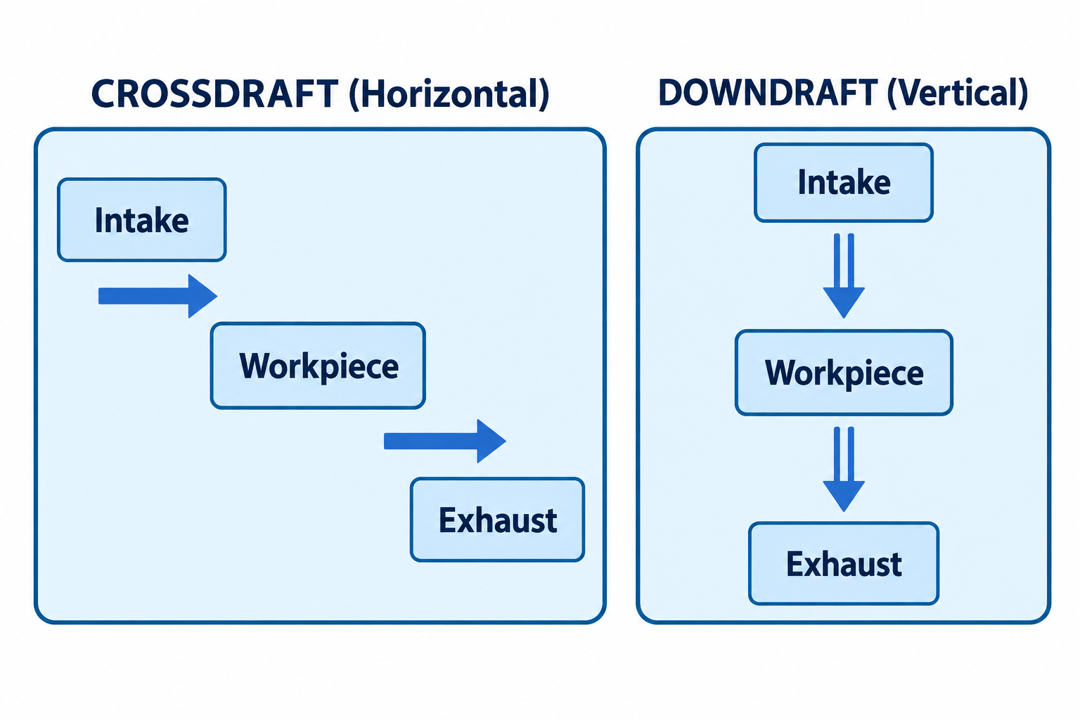
Diagram description
- CROSSDRAFT (Horizontal)
- Intake
- Workpiece
- Exhaust
- DOWNDRAFT (Vertical)
- Intake
- Workpiece
- Exhaust
- Intake → Workpiece: horizontal airflow
- Workpiece → Exhaust: horizontal airflow
- Intake → Workpiece: downward airflow
- Workpiece → Exhaust: downward airflow
- CROSSDRAFT (Horizontal) → Intake: contains
- CROSSDRAFT (Horizontal) → Workpiece: contains
- CROSSDRAFT (Horizontal) → Exhaust: contains
- DOWNDRAFT (Vertical) → Intake: contains
- DOWNDRAFT (Vertical) → Workpiece: contains
- DOWNDRAFT (Vertical) → Exhaust: contains
- Two enclosed airflow panels: CROSSDRAFT (Horizontal) contains Intake at upper-left, Workpiece center, Exhaust lower-right, with two rightward flow arrows showing Intake toward Workpiece toward Exhaust.
- DOWNDRAFT (Vertical) has Intake at top boundary, Workpiece center, Exhaust at bottom boundary, downward arrow above workpiece and downward flow line below.
Horizontal Airflow Across the Work
Horizontal crossdraft airflow moves parallel to the floor. Air enters one end of the booth—either through open-face access or filtered front doors—and travels down the length of the cabin to an exhaust filter bank positioned at the opposing end.
The GFS Performer ES installation manual details an enclosed crossdraft example that combines filtered front product doors with a rear-wall exhaust plenum. In this setup, clean air enters at the front of the cabin and exits out the back.
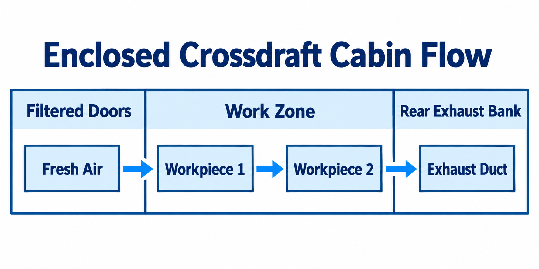
Diagram description
- Enclosed Crossdraft Cabin Flow
- Filtered Doors
- Work Zone
- Rear Exhaust Bank
- Fresh Air
- Workpiece 1
- Workpiece 2
- Exhaust Duct
- Fresh Air → Workpiece 1
- Workpiece 1 → Workpiece 2
- Workpiece 2 → Exhaust Duct
- Filtered Doors
- Fresh Air
- Work Zone
- Workpiece 1
- Workpiece 2
- Rear Exhaust Bank
- Exhaust Duct
- Title Enclosed Crossdraft Cabin Flow.
- One enclosure divided into three adjacent ordered compartments: Filtered Doors contains Fresh Air; Work Zone contains Workpiece 1 and Workpiece 2; Rear Exhaust Bank contains Exhaust Duct.
- Horizontal RIGHTward sequence Fresh Air → Workpiece 1 → Workpiece 2 → Exhaust Duct across compartments.
This horizontal vector has clear process consequences:
- Downstream overspray drift: Air picks up atomized overspray from the gun and carries it horizontally toward the back wall. Any workpiece positioned between the spray gun and the exhaust bank sits in the path of that overspray cloud. Spray sequence and part placement should be evaluated against the coating process and equipment guidance to limit downstream contamination.
- Workpiece profile interference: Wide, flat items (such as vehicle hoods or large metal sheets) oriented perpendicular to the airflow act as dams. They disrupt horizontal air velocity, creating dead zones and turbulence behind the part where overspray lingers.
- Low structural disruption: Crossdraft models exhaust through rear walls or side plenums above the floor. Common rear-exhaust configurations avoid an underfloor exhaust pit; other site work depends on the selected design.
Vertical Airflow and Floor Exhaust
Downdraft systems introduce ceiling-to-floor downdraft airflow. Conditioned air enters through an overhead plenum equipped with diffusion filter media, flows downward in a uniform vertical column around the workpiece, and exits through floor filtration.
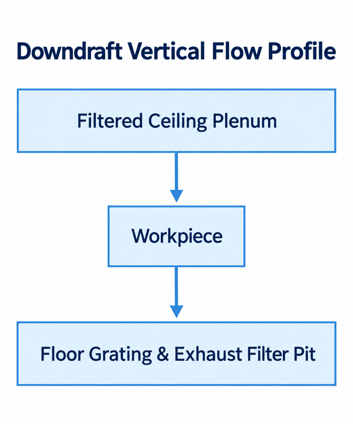
Diagram description
- Downdraft Vertical Flow Profile
- Filtered Ceiling Plenum
- Workpiece
- Floor Grating & Exhaust Filter Pit
- Filtered Ceiling Plenum → Workpiece
- Workpiece → Floor Grating & Exhaust Filter Pit
- Title Downdraft Vertical Flow Profile; Filtered Ceiling Plenum → downward Workpiece → downward Floor Grating & Exhaust Filter Pit.
- Workpiece box narrower than upper/lower boxes.
This vertical vector alters the spraying dynamic:
- Rapid overspray removal: Air draws overspray toward the floor exhaust rather than across the full cabin length. Actual capture and contamination depend on airflow, part geometry, placement, and spraying technique.
- Workpiece profile considerations: Ceiling-to-floor airflow changes how air moves around horizontal and vertical surfaces, but parts can still obstruct flow. Evaluate the actual loading arrangement rather than assuming universal coverage.
- Civil floor interfaces: True downdraft designs require a return path underneath the booth floor. This is achieved either by excavating concrete pits lined with exhaust filters and steel grating or by mounting the cabin on a raised steel basement equipped with vehicle access ramps.
Facility Preparation and Regulatory Baselines
Downdraft and crossdraft systems place distinct demands on the surrounding building. As detailed in GFS installation manuals, site preparation requires confirming a level floor across the entire cabin perimeter, verifying clearance around external exhaust housings and overhead fan motors, planning direct duct routing through the roof deck, and confirming incoming electrical service against equipment design drawings.
Maintaining proper performance requires disciplined preventative upkeep. GFS operations and maintenance documentation specifies routine inspections of intake and exhaust filter loading, cabin pressure seals, door latches, lighting tubes, make-up air burners, and exhaust fan belts. Premature loss of cabin velocity or rising particulate levels should be evaluated by qualified maintenance personnel rather than assumed to be inevitable equipment aging; clogged filters, worn belts, or imbalanced damper settings are possible causes to investigate.
Building interfaces must also meet safety codes. OSHA standard 1910.107 governs spray finishing using flammable and combustible materials. For covered operations, it addresses smooth, cleanable cabin interiors, mechanical ventilation, separation from combustible materials, and electrical precautions. The applicable requirements need project-specific review. Crucially, section 1910.107(b)(3) addresses floor safety: where the floor of a spray booth or operator station is combustible, it must be covered with a noncombustible material. This requirement establishes fire protection minimums; it does not mandate specific epoxy floor treatments for every industrial installation. Facility planners must ensure that paint booth floors and walls satisfy both municipal fire codes and operational wash-down demands.
Equipment Comparison and Selection Criteria
Choosing the appropriate cabin configuration requires matching your coating specifications, part geometries, and building infrastructure.
Configuration Comparison Matrix
| Evaluation Factor | Open-Face Crossdraft | Enclosed Crossdraft | Enclosed Downdraft |
|---|---|---|---|
| Primary Air Vector | Horizontal (front to rear) | Horizontal (front to rear) | Vertical (ceiling to floor) |
| Part Entry Style | Open face; no doors | Filtered product doors | Filtered product doors |
| Air Intake Source | Direct plant shop air | Filtered through door banks | Filtered through ceiling |
| Overspray Path | Across downstream parts | Across downstream parts | Directly down into floor |
| Floor Construction | Standard level concrete | Standard level concrete | Concrete pit or raised basement |
| Part Loading Profile | Conveyors, carts, hoists | Roll-in carts, driven vehicles | Roll-in carts, driven vehicles |
| Finish Evaluation | Assess plant-air cleanliness | Assess intake filtration and part placement | Assess filtration, floor exhaust, and part placement |
Practical Application Scenarios
Scenario A: High-Mix Structural Steel Fabrication
A shop sprays machinery frames, welded skids, and agricultural components using single-stage polyurethane and epoxy primers. Parts arrive intermittently via overhead crane or forklift carts.
- Candidate to evaluate: Open-face crossdraft.
- Rationale: Adding doors creates continuous loading delays. If the specified finish tolerates the actual plant-air conditions, open access may be a useful trade-off for easier material handling. Compare complete equipment and site costs.
Scenario B: Fleet Vehicle and Equipment Repair
A commercial repair shop finishes delivery vans, utility boxes, and municipal trucks. The building has an existing post-tension concrete slab that cannot be saw-cut or trenched for an exhaust pit.
- Candidate to evaluate: Enclosed crossdraft.
- Rationale: The enclosed envelope isolates overspray from the active body shop and filters incoming air to prevent dirt inclusions. The horizontal airflow avoids floor trenching, exhausting through a framed rear wall assembly directly through an exterior wall or roof penetration.
Scenario C: High-Volume Automotive Refinish or Aerospace Components
A production facility applies multi-stage basecoat/clearcoat systems where any airborne lint, dust nib, or overspray settlement causes rework. The facility has space for concrete pit excavation or clear ceiling height for a raised basement ramp.
- Candidate to evaluate: Enclosed downdraft.
- Rationale: Vertical airflow draws overspray toward floor exhaust and may suit the process. Evaluate finish requirements and part placement alongside the cost and feasibility of the floor interface.
Intermediate Hybrid Designs
To avoid oversimplifying your layout options, consider two common transitional designs:
- Semi-Downdraft: Air enters through ceiling filters located at the front of the booth and travels diagonally downward toward an exhaust bank positioned at the rear floor level. It provides downward airflow over the front of the vehicle without requiring an excavated floor pit.
- Side-Downdraft: Air enters through a full-length filtered ceiling plenum and is drawn down toward the floor, then turns horizontally outward into exhaust plenums built into the lower side walls. This delivers downdraft flow patterns over parts while keeping the concrete slab flat.
Planning Your Equipment Proposal
Before requesting equipment specifications, define your production constraints to evaluate practical paint booth options.
| Part Dimensions & Weight | Cabin Clearance |
|---|---|
| Daily Part Count / Mix | Door Style & Access |
| Coating Defect Tolerance | Intake Filtration Envelope |
| Concrete Slab Limitations | Exhaust Path (Pit vs. Wall) |
| Electrical & HVAC Capacity | Fan Power & Air Make-Up |
To choose the right paint booth size, start by measuring your largest workpiece. Include fixtures, handling equipment, operator access, and the selected manufacturer’s working-clearance requirements. Compare these internal dimensions against your building’s clear hook height, overhead structural trusses, and exterior wall clearances.
Prepare answers to the following operational questions before finalizing your configuration:
- What are your maximum workpiece dimensions and loading methods? (Forklift, overhead rail, wheeled cart, or drivable equipment.)
- What finish quality does your client or QA standard require? (Prime-only, industrial commercial, or high-gloss multi-stage.)
- What are the concrete slab specifications in your facility? (Standard slab, post-tension slab prohibiting trenching, or new construction allowing a pit.)
- How will booth exhaust impact plant make-up air? (Available unconditioned replacement air versus the need for a dedicated, heated Air Make-Up Unit.)
When you have these project dimensions, finish specifications, and plant layout boundaries ready, contact our team to request a project quote matched to your operational footprint.
Sources
- https://globalfinishing.com/wp-content/uploads/2018/04/GFS_open_face.pdf
- https://globalfinishing.com/wp-content/uploads/2023/11/Performer_ES_Installation_Manual.pdf
- https://globalfinishing.com/wp-content/uploads/2020/09/Auto_Refinish_Service_and_Ops_Manual.pdf
- https://www.paintbooth.com/how-to-choose-the-right-size-paint-booth-for-your-operations/
- https://www.paintbooth.com/do-paint-booths-require-special-flooring-or-walls/
- https://www.paintbooth.com/paint-booths/
- https://www.paintbooth.com/quote/
- https://www.osha.gov/laws-regs/regulations/standardnumber/1910/1910.107